MAGUS
제품문의
기술문의
혁신, 신뢰, 협업
자동차 R&D 파트너
Track Testing Laboratory Testing Driving Simulators GPS+IMU Sensor & Transducers Consultancy Work
Suspension system NVH testing
What is NVH?
Noise, vibration, and harshness (NHV) is a field dedicated to the analysis and mitigation of noise and vibration attributes in vehicles. It’s a critical aspect of vehicle design, affecting both performance and user experience. NHV testing involves exposing a complete vehicle, or a component or subassembly to vibrations across various frequencies. This helps in identifying potential issues or annoyances.

NVH issues can often remain undetected until late in a vehicle development programme, which can lead to costly and compromised corrective measures. Our ANVH 250 test machine enables accurate measurement of suspension system NVH transmission long before prototype vehicles are available.
The ANVH 250
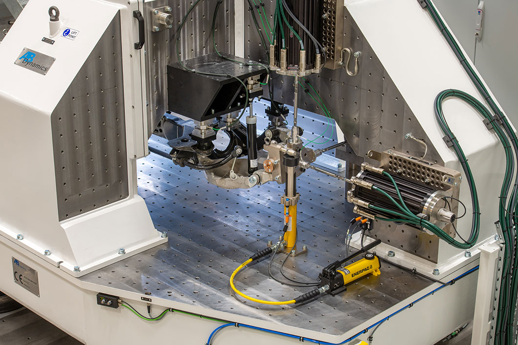
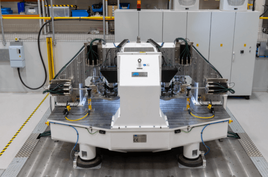
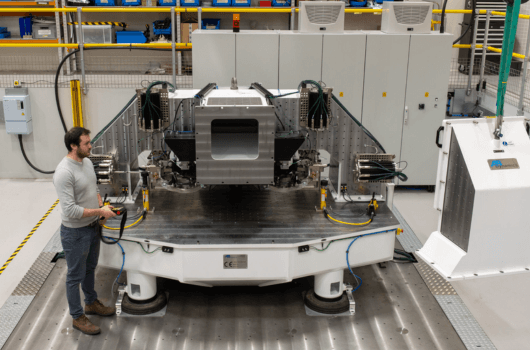
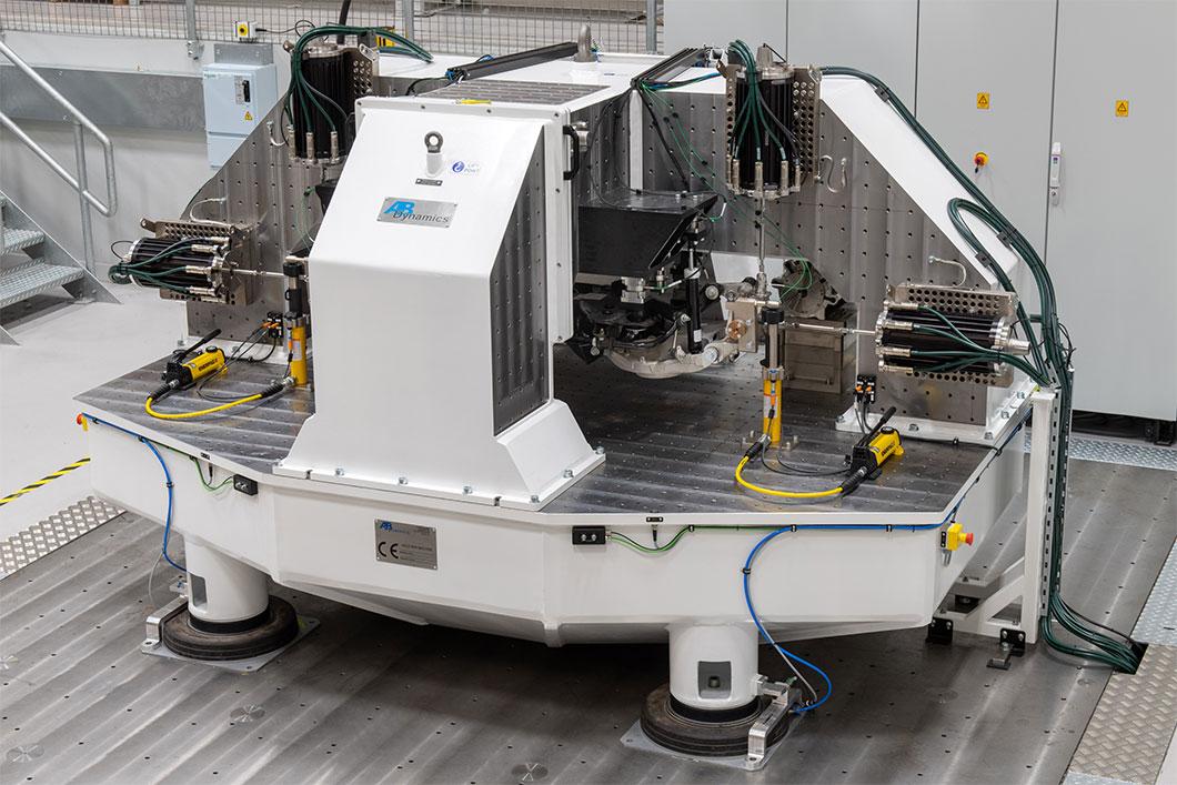
The ANVH 250 measures the transfer path of structure-borne noise induced by a vehicle suspension’s interaction with the road surface early in the development process. The ANVH 250 is designed to allow a wide range of vehicle sub frame assemblies to be loaded and fixed to the frame with custom mounts. It also has the option to be fitted with the Dynamic Arm wheel position measurement system from our SPMM Plus to enable basic kinematics and compliance (K&C) characteristics of the axle subframe to be measured.
How the ANVH 250 works
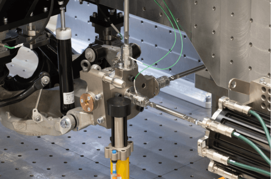
The ANVH 250 simulates the structural propagation of vibrations from the tyre contact patch through the suspension system to the vehicle body by injecting high-frequency test signals into the axle spindles. Up to six bespoke electro-magnetic actuators apply precisely controlled motion at frequencies from 0-250Hz and displacements from +/-0.01 to +/-50mm, while tri-axial load cells measure the forces transmitted to each vehicle body mounting point.

The ANVH 250 can apply sinusoidal, random input and road load data displacements to the suspension system. Displacements can be applied to the wheel hubs in the vertical (Z), longitudinal (X) or lateral (Y) directions. The paired displacements at the hubs can be in-phase, anti-phase or single-sided. By analysing the resultant forces, accelerations and displacements, sources of structural resonance can be identified, isolated and optimised.
Downloads
Brochure